Skip to content

Translate drawing requirements
into machining decisions.

Industry reference photo · Not a RayTech facility
Understand machiningProcess Selection
Define engineering requirementsEngineering Requirements
Prepare drawings and RFQRFQ Preparation

Custom machining:
where should you
start?

01 /

Drawing and geometry review

Identify 3D geometry, 2D dimensions, assembly datums and unusual features.

02 /

Process and material selection

Consider milling and turning alongside material and finish requirements.

03 /

Inspection, volume and timing

Define acceptance criteria, order volume and target schedule as review inputs.

Find a machining process
that fits the geometry.

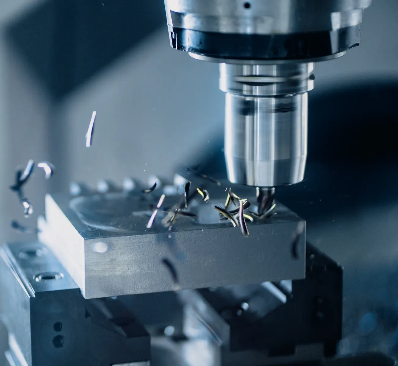
Industry process reference photo, not RayTech equipment

CNC Milling / Machining Centers

An overview of planes, pockets, holes and complex non-rotating parts.
↗
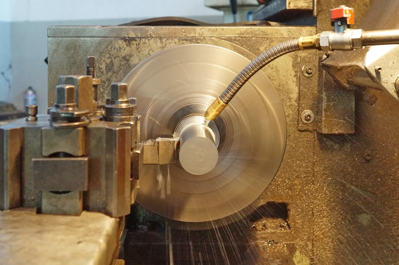
Industry process reference photo, not RayTech equipment

CNC Turning

An overview of shafts, bushings, rings and rotational parts.
↗

Consider materials
and surface finishes together.

Generic metal industry photo, not certification of a material grade or RayTech product
01 / ALUMINUM

Aluminum

Evaluate weight, stiffness and surface requirements.
Generic metal industry photo, not certification of a material grade or RayTech product
02 / STAINLESS

Stainless steel

Consider corrosion resistance and machining conditions.
Generic metal industry photo, not certification of a material grade or RayTech product
03 / STEEL

Carbon and alloy steels

Consider heat treatment and wear requirements.

Generic metal industry photo, not certification of a material grade or RayTech product
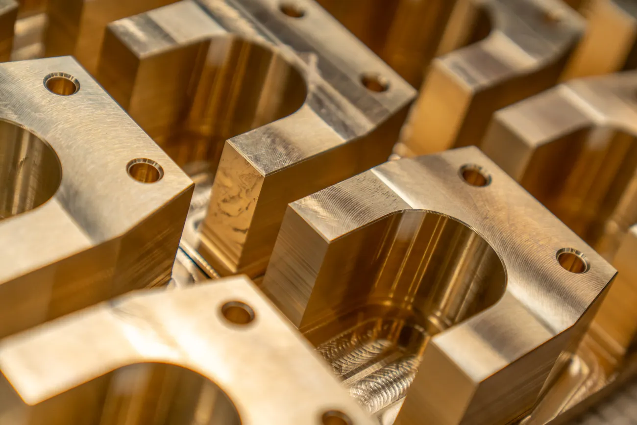
04 / COPPER ALLOY

Copper alloys

Review conductivity and functional dimensions.

Surface finishing guidanceAnodizing, plating and blasting are examples of finishing processes to be assessed based on part requirements and actual supplier scope.Prepare requirements ↗

Review machining
conditions through
technical evidence.

TOPICTECHNICAL INPUTREVIEW CRITERIA
Available operationsMilling / turning / other processesProcess fit and tool accessibility
Part dimensionsMax X/Y/Z · diameter/lengthPart dimensions and fixturing
Dimensional tolerancesConditions by feature and datumFunctional versus general tolerances
Materials handledGrades and stock formsMaterial grade and stock condition
Quantity rangePrototype / repeat-order termsPrototype and repeat-order scope
Inspection and documentsInspection equipment and recordsInspection methods and records

Small geometry details
can change the manufacturing review.

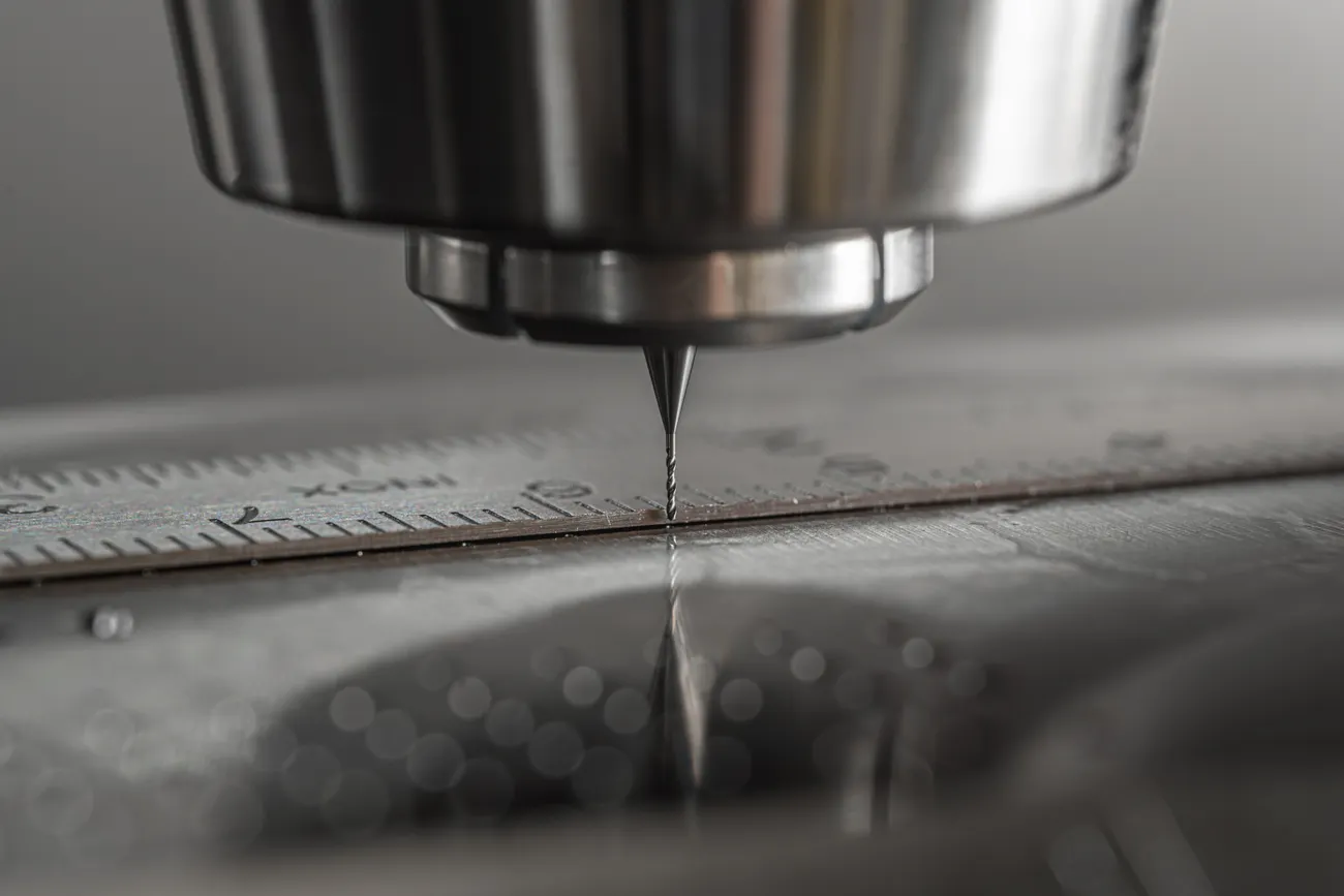
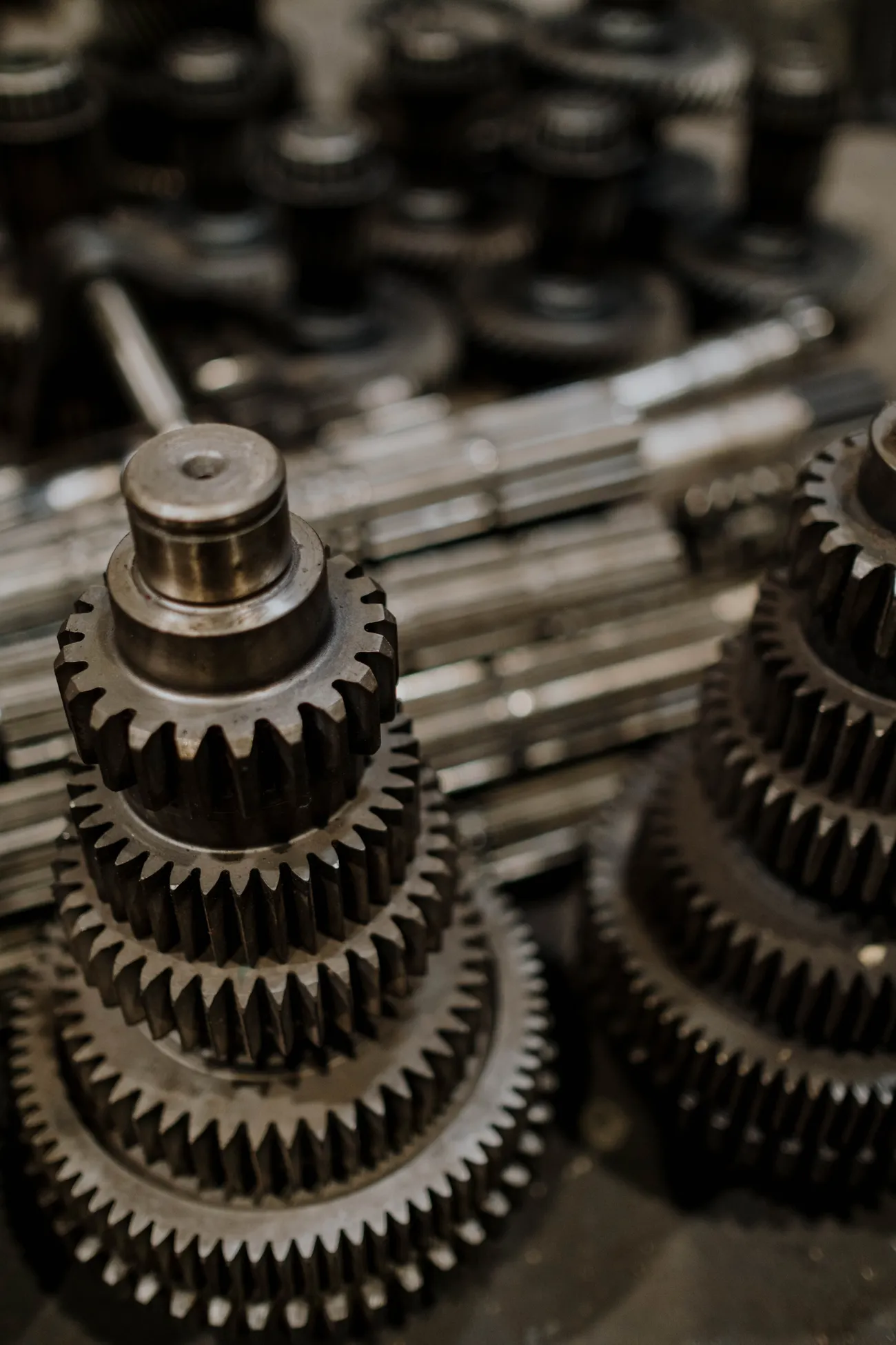
Machining reference photo · Not RayTech equipment
01 /

Internal radii and corners

Tool access and internal corner geometry may need additional evaluation.

02 /

Holes, threads and depth

Mark hole depths and thread specifications clearly on the 2D drawing.

03 /

Thin walls and long features

Part deflection and fixturing may affect the process.

04 /

Functional dimensions and tolerances

Make critical assembly datums and tolerances easy to identify.
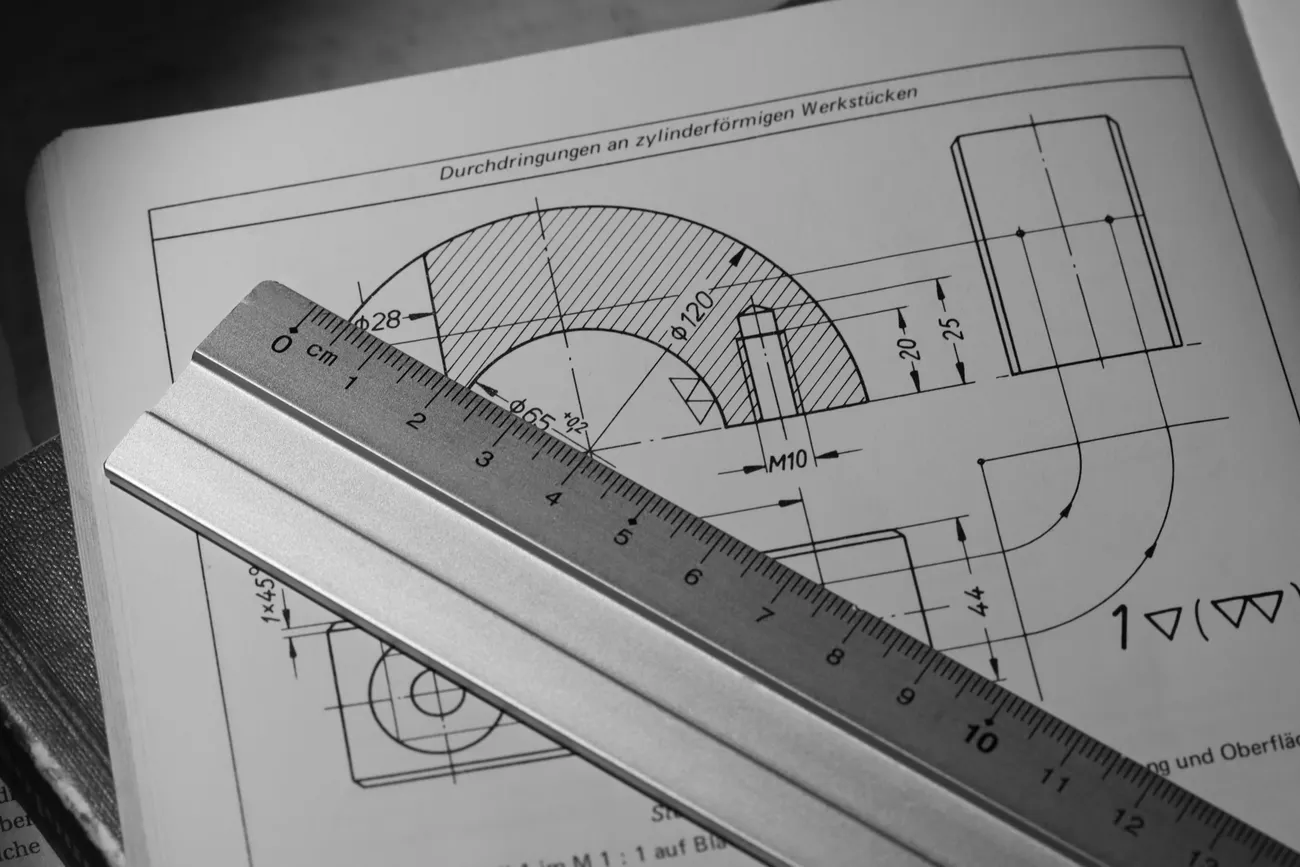
Engineering drafting reference · Not customer drawings

Prepare drawings
for an efficient review

  • 01 3D model — STEP/STP where available
  • 02 2D drawing — functional dimensions and tolerances
  • 03 Material grade, quantity and intended use
  • 04 Finish, inspection and target schedule

Main factors affecting
a CNC quotation

01Material and stock formGrade, condition and stock form change material and processing requirements.
02Geometry and machining timeAccessibility, tool changes, fixturing and process steps affect scope.
03Quantity and repeat ordersOrder volume and repeatability affect setup and unit-price structures.
04Tolerances and inspectionReview critical dimensions, measurement conditions and document needs.
05Finishing and timingSurface requirements and schedule constraints are part of the scope.

OEM collaboration starts
with clear stages.

STEP 01

Requirements brief

Collect geometry, grade, quantity and requirements

STEP 02

Drawing review

Review potential process and missing details

STEP 03

Quotation discussion

Review volume, conditions and timing

STEP 04

Production scope agreement

Agree responsibilities and inspection requirements

STEP 05

Inspection and delivery

Confirm accepted output and delivery terms
Quality starts with
clear engineering
requirements.

Explore related questions
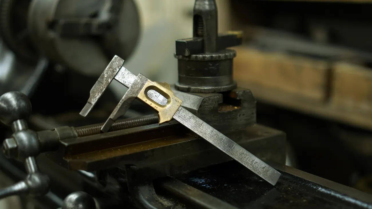
Measurement reference photo, not RayTech inspection equipment

Technical criteria
for supplier selection

Manufacturing operations and machines

Consider part geometry, working envelope and process selection.

Part geometry and requirements

Review material, geometry, volume and functional requirements.

Quality and inspection criteria

Identify critical dimensions, measurement methods and records.

Technical communication and project responsibility

Clarify drawing revisions, acceptance and delivery responsibilities.

Frequently asked
technical questions

Can a 2D drawing support technical review?

2D drawings describe dimensions and tolerances, while STEP/STP models help convey complex geometry.

What is the difference between milling and turning?

Milling typically uses a rotating cutting tool for non-rotational shapes; turning rotates the workpiece for features such as shafts and bushings. Hybrid parts need further review.

How should critical tolerances be identified?

Mark dimensions affecting fit or function, together with measurement criteria and any required inspection records.

What information is useful for an RFQ?

Prepare geometry, material, quantity, critical tolerances, finishes and target schedule.

Have your drawings ready?
Prepare the details for future review.